The Electrical Board
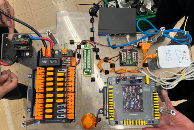
For reference, this was last year's eboard
Purpose
The Electrical Board (E-Board) is the hub that contains all the electrical components of the robot. The electrical components are what give the robot signals to run. The E-board is located on one panel of polycarbonate, providing for easy maintenance.
E-board placement
This year we decided to place the E-Board on the bellypan of the robot. It is important to ensure that the e-board is placed in a manner where it is safe from impact collision yet easy to access. The 2025 FRC game places emphasis on taking advantage of the height of the robot. This leaves space on the bottom for the E-Board components. Some components are scattered throughout the robot to provide for optimal efficiency. For instance, the Radio is located on the arm of the intake. With the majority of the motors being positioned towards the bottom of the robot, it made logical sense to place the rest of the E-Board near it. By placing it towards the back center of the robot, the equipment would be protected from any collisions, and would not interfere with any mechanical parts.
Components
- 12 volt Lead Acid Battery
- 120A Circuit Breaker
- Power Distribution Hub (PDH)
- RoboRio 2.0
- Robot Signal Light (RSL)
- NavX2
12 Volt Lead Acid Battery
The MK ES17-12 battery provided by AndyMark is capable of supplying 100 amperes per hour of energy, and is the cornerstone of the robot, providing the entity with power. The battery is connected to the Power Distribution Hub supplied by Rev Robotics and a 120 amp circuit breaker.
120 Ampere Circuit Breaker
The circuit breaker is the first line of defense between the 12V battery and the rest of the E-Board that protects against any abnormal fluctuations. Without this essential piece, the board would be at the risk of shorts. Furthermore, it serves as an on/off switch for the robot.
Power Distribution Hub (PDH)
Please note that we will be using the PDH, NOT the PDP. On wpilib look at the REV diagram NOT the CTR diagram.
The Power Distribution Hub serves as the power center of the robot. It is capable of taking the power from the 120 Volt Lead Acid Battery and facilitating that power to other electrical components like motor controllers, the voltage regulator module, and RoboRio. It has 20 high current channels and 3 lower current channels. It plays a vital role in terminating the CAN and provides additional functionality with an LED display for the voltage. The display helps identify shorts.
Specifications: The PDH supplies 30-40 amps per motor controller, depending on the specification and necessity, with individual circuit breakers in addition to handle this load. In addition, 10-20 amps are supplied to the Voltage Regulator Module and roboRIO through the low current channels, with circuit breakers as well.
We use this to distribute power to the entire robot. Please make sure that you understand which fuses to use, and how to wire CAN to the PDH.

- Use this link, and you can scroll to the bottom and click around to get more information pertaining the PDH (We suggest looking at Wiring it, the status LED patterns, and learn how to troubleshoot it) PDH information
- Make sure you understand its capabilities and features
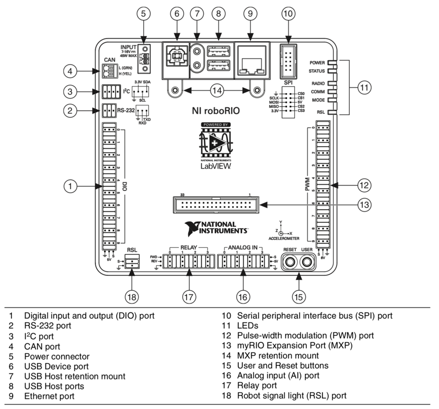
roboRIO 2.0
The roboRIO 2.0 is the nerve center of the robot that takes information from sensors, cameras, and other electrical components, delivering them to the driver and executing commands. The roboRIO 2.0 starts the CAN chain for the motor controllers and contains other functionality like DIO for limit switches and PWM for specific motor controllers.
The RoboRIO is the motherboard of the robot. The I2C port, SPI port, and RS232 Port on the roboRIO are sometimes used. Do understand how to wire the RSL, any sensors (Digital and analog), cameras, servos, how to connect it to the CAN bus and how to power it. Here is a very basic walkthrough of the roboRIO
Voltage Regulator Module (VRM)
Can increase/decrease (step up/step down) voltage that goes through it. We use this for the Network switch and for the radio.

PCM (Pneumatics Control Module)
As of now, do not have the new PCM, so for the PCM study the old PCM (the CTR one)
- We use the PCM to control the compressor, the pressure switch, and the solenoids.
- It can support both 12V and 24V solenoids
- We must manually adjust the jumper in the VSOL slot, to switch between 12V and 24V (we can't use both at the same time)
- Powered directly by the PDH, and uses CAN to communicate with the e-Board

Radio and Network Switch
The VH-109 Radio is in charge of delivering information from the cameras to the driver during competition. The radio is powered with 12 volts from the Power Distribution Hub, and it tethered to the roboRIO 2.0 via the ethernet ports. It is capable of operating on different frequencies, WI- FI 2.4G and 6E, and connecting to 2 cameras.
- The radio lets us wirelessly communicate with the robot
- The network switch gives us access to more ethernet ports
- The wiring for the new radio is a bit different. See this diagram

- We can either use the VRM 12V 2A port or the PDH low current channel to power it. Then the ethernet goes from the roboRIO to the rio port on the radio, On the other side we get the ethernet from the DS port, and not the AUX1 port.
- Scan through this website. Ignore the mechanical specifications/diagrams. Instead focus on mounting options, status LEDS, the ports, etc. VH-109 FRC Radio
- This is a network switch
Jetson Orin Nano
The Jetson Orin Nano by Nvidia serves as an on board computer for the robot that can be used to handle high demand tasks such as processing data from cameras and sensors.
NavX2
The NavX2 is in essence a motion processor that is in charge of compiling data from gyroscopes and accelerometers to follow an outlined path or rotate to a specific angle.
Robot Signal Light (RSL)
The Robot Signal is imperative in visually providing cues. There are three settings that the RSL may occupy at any time. A solid light means that the Robot is ON and DISABLED. A blinking light means that the Robot is ON and ENABLED. No light means that the robot is off.
LEDs
We have two LED strips mounted on either side of the robot that provide visual cues for drivers and human players. For example, the LEDs will change colors for different heights of the elevator, flash when the robot is ready to intake, and flash when the robot is ready to score on a reef branch. This allows for ease and comfort of driving as the robot indicates its current configuration.